
|
2017 Environment |
||||
|
Determining nitrogen reduction yield on two parts of a wastewater treatment plant (lamellar clarifier and trickling filter) DUMAS Estelle |
||||
|
Introduction In a water treatment plant, many successive steps of treatment enable wastewater to be treated. Lamellar clarifier and trickling filter are broached. Suspended solids present in the water are decanted in the lamellar clarifier. As for the trickling filter, it constitutes a biological treatment because of the different microorganisms which can develop on polyethylene bands. The wastewater goes inside this structure from the top, and it flows along each band. These two steps reduce mass concentrations of some nutrients including nitrogen. A calculation of the yield is made through spectrophotometric quantitative analysis. Experimental conditions Samples were collected in three different places : at the entrance and exit of the lamellar clarifier, and also at the exit of the trickling filter. Micro methods were used for the analysis. These methods were cuvette tests. LCK 338 tubes were used. The cuvette test was a kit containing reagents A, B, C et D. The operating procedure was : The beaker containing the sample was homogenized by magnetic stirring. 0.2 mL of samples were removed and put in a tube. Then, 2.3 mL of reagent A were added in the tube and one pastille B. The tube was closed, and was heated for 1h at 100 °C. When the tube came back to room temperature, one capsule C was added. To dissolve the capsule powder, it was necessary to shake it. In this tube, 0.5 mL were removed and placed in a micro method tube. Finally, 0.2 mL of reagent D were added. The tube was closed and shaken, and it was necessary to wait for 15 min at room temperature. The result was directly read on the spectrophotometer at λ of 345 nm in mg/L. This last wavelength means the solution absorbs in the ultraviolet ray area. Results Results are visible in the percentage table. With the spectrophotometer, the results were obtained in mg/L, and after, a yield was calculated between the entrance of the treatment structure and its exit. The study was carried out only two days because of a lack of time and a delay problem with the material installation. The lamellar clarifier yield seems constant contrary to the trickling filter yield. The result means 14% of the nitrogen, present in the wastewater before the lamellar clarifier treatment, was eliminated. Regarding the trickling filter, two results was not sufficient to conclude, indeed the result obtained the 18/04 was roughly twice the result obtained the 11/04. Conclusion The study allowed us to check the nitrogen reduction yield on two steps of a wastewater treatment plant. It also shows that these two steps eliminated a small percentage of nitrogen in the wastewater. So, most of the nitrogen reduction is probably made by another treatment and particularly a biological treatment. |
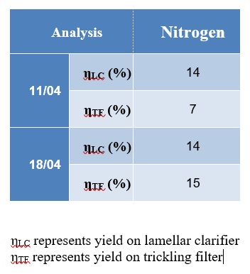 Table of nitrogen reduction yield on lamellar clarifier and trickling filter |
|||
|
SUEZ Eau France SAS Station d'épuration |
|
|||
ANALYSE & CONTROLE, le MASTER Batiment Bertholet - 22 avenue Gaston Berger 69622 Villeurbanne Phone : 04-72-44-79-88 mail : master-analyse-controle@univ-lyon1.fr |
DIRECTOR Jerome RANDON SECRETARY |
TECHNICAL STAFF Herve DELEPINE Julie BERTRAND Didier FOURNIER |
EDITORIAL OFFICE Editorial Director : Jerome RANDON webmastering : Chahira YAHIAOUI |